Creating Aquaplaning Feature Definition
A Feature definition for Aquaplaning controls the symbology of two different types of entity (linear and surface) which are produced by running the "Aquaplaning" command. The linear elements represent the water film depths at regular locations on the road surface. The surface element is a delta terrain model, created using the linear elements, so it represents the water film depths over the whole road surface.
You want to make sure that both of these places use the same values.
- The Thematic template for the surface is used to display the delta terrain model.
- The Aquaplaning Settings in Preferences are used for the linear elements.
When setup correctly, the graphical result of the Aquaplaning tool will be a colour coded set of linear elements and a delta terrain model, and the colours will make it easy to pinpoint areas of concern - those where the risk of aquaplaning occurring is high or unacceptable.
The following steps take you through creating a feature definition to use in the Aquaplaning tool. They should be done in a DGNLIB, so that the feature definition can be reused and will not be lost if the DGN is deleted.
The aquaplaning Feature Definition refers to five Feature symbologies, which in turn refer (via Element Templates) to a Display Style. Set up the Display Style first.
Create Display Style
The display styles dialog is shown.
- Find and click Thematic: Height in the list on the left and then copy the style using the button on the toolbar. Rename the new one by right clicking the new name.
This is a good baseline from which to start.
- Activate the new display style with a double click.
 Check the Ignore lighting box to
ensure the bands of colour shown are not shaded and then select the button next
to Thematic Display.
Check the Ignore lighting box to
ensure the bands of colour shown are not shaded and then select the button next
to Thematic Display.
The following dialog is displayed: (Note the dialog disappears when escape is pressed, or focus is lost in some other way.)
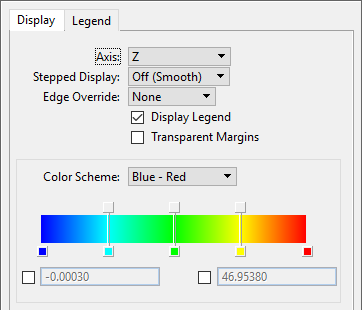
Next, for aquaplaning define specific ranges of water film depth.
-
Change the Count from 10 to 3
-
Change the values on the panel to suit - for example by using the depth ranges for low, acceptable, and high risks.

Note that it's not possible to change a number to a value which causes an overlap with another min/max band, so the order in which values are changed requires some thought.
Note also that the margin colour has been altered to the same value as the highest band. This ensures anything outside the ranges specified appears to match the higher band. This colour could also be used to denote an unacceptable risk.
Save the setup created for later use.
Now set up the Feature Symbologies and Element Templates.
Create Element Templates (and initial Feature Symbology)
- Show the Explorer and Properties panels.
- Expand Feature Symbologies in the OpenRoads Standards panel.
- Right click Surface and create a new category. Give it an appropriate name, such as Aquaplaning.
- Right click the new aquaplaning category and select New feature Symbology. Rename it to AquacThematic or similar.
- In the properties window, find Default Element Template and expand the dropdown as shown.
- Select Manage Templates...
Now create a template to control how the surface will display.
- In the dialog that appears, expand the tree node for the current DGN or DGNLib, and right click.
- Select New Template and rename it to aquaplaning thematic.
- Right click on aquaplaning thematic and select Add > Terrain Model > Calculated Features.
- Repeat the above but select Add > Terrain Model > Display.
Several extra groups of options appear on the right of the panel.
- Find Contours in the CalculatedFeaturesDisplay group and ensure it is switched off. Ensure Triangles are switched on in the same group.
- Find Triangles->ThematicDisplayStyle in the CalculatedFeatureSettings group. using the dropdown, find and select the display style you just created.
- To save a little time, set up the linear element templates while in this panel. The Linear Templates are what you use to draw the flowlines.
- Right click the Linear node in the tree and select New Template Group. Change the name of the new group to "aqua" or similar.
- Right click the new group and select New Template. Rename the new template to Low Risk or similar.
- The right-hand side shows some basic display options for the template. Change the colour to Green, and change other settings, such as the Level, if needed).
- Repeat these last few steps to create another three linear templates, for Acceptable Risk, High Risk, and Unacceptable Risk.
- Close the Element Templates panel.
Now, back in the Explorer, resume setting up feature symbologies.
Finish Creating Feature Symbologies
- Expand the dropdown box next to Default Element Template and scroll to find aquaplaning thematic or whatever you called your terrain template.
- Select it.
The terrain component's symbology is complete. The linear components are next.
- In Explorer, right click on Linear (under Feature Symbologies) and choose new Category.
- Rename the new category to Aquaplaning.
- Add a new Feature Symbology by right clicking on the new aquaplaning category. Rename it to Low Risk (or similar).
In the properties window, you should see a "Default Element Template".
- Under the dropdown list of element templates, find and select the appropriate linear element template - the one with the correct settings for this level of risk.
- Repeat the last few steps to set up Feature Symbologies for the other three Element Templates.
- Five feature symbologies are set up now - four for linear, and one for the surface. Next create the feature definition which references them.
Create the Feature Definition
- Back in Explorer, expand Feature Definitions. You should see an Aquaplaning entry in the tree.
- Right click on Aquaplaning and select New Feature Definition. Rename it to My Aquaplaning (or similar).
- Select the new Feature Definition to see items in the properties window. Under the "Aquaplaning" panel, select the appropriate feature symbology for each of the five Feature Symbology fields.
Your new feature definition is now set up.
- If you're working in a DGNLIB, now is the time to restart the product, and confirm that the DGNLib is being loaded automatically. This should happen if it has been named correctly, and you place it in the correct folder. For example, in the Training and Examples workspace, and the Training - Metric workset, if the DGNLib has *Feature* in its name, and it is placed in a folder that is defined by the CIVIL_CONTENTMANAGEMENTDGNLIBLIST config variable, such as C:\ProgramData\Bentley\OpenRoads Designer CE\Configuration\Organization-Civil\_Civil Default Standards - Metric\Dgnlib\Feature Definitions, then it will be loaded automatically.
- Speak to the person who looks after your workspace if you are unsure about this.